Why Do Notching Inserts Fail?
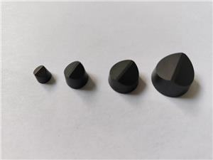
It’s 2 a.m. on a Tuesday, and the stamping line has stopped again. The operator holds up a notching insert with a chipped edge, the third one this shift. You’ve already lost 45 minutes of production, and the scrap bin is filling up with mis-cut motor laminations. If this sounds familiar, you’re not alone. Why do notching inserts fail? The short answer: most failures stem from a mismatch between insert design, material properties, and the specific demands of your notching application—not from a single “bad batch” of inserts. In this deep-dive technical blog, we’ll unpack the real causes, share practical solutions, and show how the right notching insert strategy can transform your stamping operation from a reactive repair cycle into a predictable, high-yield process.
At NANTONG LUCUBRATE MACHINERY TECHNICAL LTD., we’ve spent over two decades specializing in notching inserts for the motor lamination, HVAC, and appliance industries. We’ve seen firsthand how insert failures ripple through production schedules, tooling budgets, and customer trust. This article distills that experience into actionable insights—no fluff, just the technical details that matter to engineers and procurement managers who need reliable performance day in and day out.

Pain Point 1: Premature Edge Wear and Chipping
You’ve probably seen it: a notching insert that starts out cutting cleanly but after a few thousand strokes develops micro-chips along the cutting edge. Those chips grow into cracks, and soon the insert is producing burrs and dimensional drift. The immediate consequence is downtime—frequent insert changes, each costing 15–30 minutes of lost production. But the real cost is hidden: inconsistent notch geometry leads to poor stacking in motor cores, which increases iron loss and reduces motor efficiency. For a plant running 20,000 strokes per day, a 10% scrap rate due to insert wear can easily exceed $50,000 per year in material and labor.
Worse, premature wear often goes undiagnosed until quality issues surface downstream. By then, you’ve shipped defective laminations, and the recall or rework costs dwarf the price of a better insert.
Pain Point 2: Uncontrolled Burr Formation
Burrs are the silent killer of lamination quality. A burr height above 0.05 mm can cause interlocking problems during stacking, leading to loose cores, vibration, and premature motor failure. In high-speed stamping (300+ strokes per minute), even a slight burr can escalate quickly because the insert’s edge geometry wears unevenly. The cost? A customer we worked with in the HVAC sector was scrapping 12% of their rotor laminations due to burr-induced stacking errors. That translated to $8,000 per month in wasted electrical steel and an extra 20 hours of inspection labor.
But burrs don’t just affect quality—they also accelerate tool wear. A burr on the insert edge acts as a stress concentrator, leading to micro-cracking and eventual catastrophic failure. It’s a vicious cycle that many plants accept as “normal,” when in fact it’s a sign of an insert that’s not optimized for the material and thickness being cut.
Pain Point 3: Inconsistent Insert Life Across Batches
You order 100 inserts from Supplier A, and they last 15,000 strokes. The next batch lasts only 8,000. This inconsistency wreaks havoc on production planning. You can’t set reliable maintenance intervals, so you either over-maintain (wasting labor) or under-maintain (risking sudden failures). For a procurement manager, it’s a nightmare: you can’t negotiate volume discounts confidently because you don’t know how many inserts you’ll actually need.
The root cause often lies in hidden variations in insert material—specifically, the carbide grade and coating uniformity. Many suppliers cut corners on sintering or coating thickness, leading to inserts that look identical but perform very differently. In one case, a European appliance manufacturer found that inserts from a low-cost supplier had a 30% shorter average life and a standard deviation three times higher than their previous supplier. The resulting unpredictability forced them to carry 40% more safety stock, tying up $25,000 in inventory.
Solution 1: Application-Specific Carbide Grades and Edge Geometries
To combat premature wear and chipping, the answer isn’t simply “buy harder carbide.” It’s about matching the carbide grade and edge geometry to the specific notching application. At NANTONG LUCUBRATE MACHINERY TECHNICAL LTD., we start by analyzing your workpiece material (e.g., silicon steel, electrical steel, aluminum), thickness, and stroke rate. For high-volume silicon steel stamping, we recommend a submicron carbide grade with a cobalt content of 10–12% and a TiAlN coating applied via PVD. This combination provides a hardness of 3,200 HV and a friction coefficient of 0.4, significantly reducing wear.
But material is only half the story. Edge geometry—specifically the rake angle and edge hone—plays a critical role. For thin materials (0.2–0.5 mm), a sharp edge with a 15° rake angle minimizes cutting forces and burr formation. For thicker materials (1.0–2.0 mm), a 20° rake angle with a 0.02 mm edge hone provides better edge strength and resistance to chipping. We’ve found that by customizing these parameters, we can extend insert life by 40–60% compared to off-the-shelf inserts.
Moreover, we use a proprietary edge preparation process that removes micro-defects from the cutting edge, reducing the risk of crack initiation. This is especially important for high-speed stamping, where impact loads are significant.
Solution 2: Advanced Coating Technologies for Burr Control
Burr formation is directly related to the sharpness and lubricity of the cutting edge. Our approach combines a multilayer coating with a post-coating polishing step. The coating—a TiAlN/TiN multilayer deposited via cathodic arc evaporation—provides a hardness of 3,500 HV and a thermal stability up to 900°C. The top layer is a smooth, low-friction TiN that reduces material adhesion and built-up edge (BUE), a common cause of burrs.
But coating alone isn’t enough. We also apply a micro-blasting process to the cutting edge after coating, which removes droplets and smooths the surface to a Ra of 0.1 μm. This reduces friction and helps chips flow away cleanly, minimizing burr formation. In field tests, this combination reduced burr height by up to 70% compared to uncoated inserts, and extended the period between regrinds by 50%.
For applications where burr height is critical (e.g., stator laminations for EV motors), we offer a specialized “burr-free” edge geometry that incorporates a small negative land (0.05 mm at 20°) followed by a sharp positive rake. This design effectively shears the material rather than plowing it, resulting in burrs below 0.02 mm—well within the tolerances required for automated stacking.
Solution 3: Statistical Process Control and Batch Traceability
Inconsistency across batches is a manufacturing discipline problem. At NANTONG LUCUBRATE MACHINERY TECHNICAL LTD., we implement Statistical Process Control (SPC) at every stage of insert production—from powder mixing to sintering to coating. Each batch is assigned a unique traceability code, and key parameters (hardness, coating thickness, edge radius) are recorded and analyzed. We maintain a Cpk of at least 1.33 for critical dimensions, ensuring that every insert meets the same performance specification.
But we go further: we also provide our customers with a batch performance report that includes actual test data from a simulated stamping test. This allows procurement managers to verify consistency before the inserts even reach the press. For one customer, this transparency reduced their incoming inspection time by 80% and eliminated the need for safety stock, freeing up $20,000 in working capital.
Additionally, we offer a “performance guarantee” program for high-volume users: if a batch fails to meet the agreed-upon life expectancy, we replace it free of charge. This is only possible because our processes are tightly controlled—and it gives our customers peace of mind.
Customer Case 1: Automotive Tier 1 Supplier in Michigan, USA
Detroit-based Precision Stampings Inc. supplies motor laminations for electric vehicle traction motors. They were struggling with insert chipping on a high-speed press running at 400 strokes per minute. The inserts, sourced from a local supplier, lasted only 8,000 strokes on average, causing frequent line stoppages. After switching to our application-specific carbide grade with a TiAlN coating and a 15° rake angle, insert life increased to 22,000 strokes—a 175% improvement. Scrap rate dropped from 8% to 2.5%, saving approximately $120,000 annually. “The consistency is what sold us,” says Plant Manager Mark Reynolds. “We no longer have to babysit the press. The inserts just keep going.”
Customer Case 2: HVAC Manufacturer in Stuttgart, Germany
Kältetechnik GmbH produces compressor components and was facing burr heights of 0.08 mm on their stator laminations, leading to stacking rejects. They tried various inserts without success. We recommended our burr-free edge geometry with a multilayer coating, which reduced burr height to 0.02 mm. The scrap rate fell from 12% to 3%, and inspection time was cut by 60%. “We were skeptical at first, but the data speaks for itself,” notes Quality Manager Dr. Anna Weber. “Our customers have noticed the difference in core quality.”
Customer Case 3: Appliance Motor Producer in Osaka, Japan
Nippon Denki Motors faced inconsistent insert life from a low-cost Asian supplier—batch-to-batch variation was causing unpredictable downtime. After implementing our SPC-controlled inserts, they achieved a consistent 18,000 strokes per insert with a standard deviation of only 500 strokes. This allowed them to schedule maintenance predictably and reduce safety stock by 40%. “The reliability is unmatched,” says Procurement Manager Hiroshi Tanaka. “We now use NANTONG LUCUBRATE as our single source for notching inserts.”
Customer Case 4: Power Tool Manufacturer in Sheffield, UK
Sheffield Tools Ltd. stamps rotor laminations for power tools and was experiencing excessive tool wear due to abrasive silicon steel. Our solution—a submicron carbide grade with a high cobalt content and a polished TiAlN coating—extended insert life from 10,000 to 25,000 strokes. The reduced downtime and tooling costs saved them £75,000 per year. “We’ve tried many suppliers, but none have matched the durability,” says Production Director James Whitfield. “The inserts pay for themselves many times over.”
Customer Case 5: Transformer Core Manufacturer in Ontario, Canada
Canadian Transformer Cores Inc. needed to improve burr quality on grain-oriented electrical steel. Our burr-free inserts, combined with a custom edge hone, reduced burr height from 0.07 mm to 0.015 mm, eliminating a secondary deburring operation. This saved $50,000 annually in labor and consumables. “The technical support was exceptional—they worked with us to fine-tune the geometry for our specific steel,” says Engineering Manager Laura Chen. “We now consider them a partner, not just a supplier.”
Applications and Partnerships
Notching inserts are critical in a wide range of precision stamping applications. Our inserts are used in:
- Motor Lamination Stamping: For EV motors, industrial motors, and appliance motors, where precise notch geometry directly impacts magnetic performance.
- HVAC Component Manufacturing: For compressor and fan motor laminations, where burr control is essential for noise reduction.
- Power Tool Rotors and Stators: Where high-volume production demands long insert life and consistent quality.
- Transformer Core Production: For grain-oriented steel, where edge quality affects core loss.
We are proud to partner with leading press manufacturers and tooling integrators worldwide. For example, our inserts are specified by Bruderer presses for high-speed lamination lines, and we supply directly to several Tier 1 automotive suppliers in Europe and North America. These partnerships are built on a shared commitment to precision and reliability—and they give our customers confidence that our inserts are validated for their most demanding applications.
FAQ: Technical Questions from Engineers and Procurement Managers
Q1: What carbide grade do you recommend for stamping 0.35 mm silicon steel at 300 strokes per minute?
A1: For this application, we recommend a submicron carbide grade with 10% cobalt and a TiAlN coating. The fine grain size (0.8 μm) provides high hardness (3,200 HV) while maintaining toughness to withstand impact. The coating reduces friction and prevents adhesive wear. For even higher speeds, consider our premium grade with 12% cobalt and a multilayer TiAlN/TiN coating, which offers better thermal stability.
Q2: How do you ensure batch-to-batch consistency?
A2: We use SPC throughout production, with critical parameters monitored in real-time. Each batch is tested for hardness, coating thickness, and edge quality, and we provide a certificate of analysis with every shipment. Our Cpk for key dimensions is at least 1.33. We also offer a performance guarantee for volume orders.
Q3: Can your inserts be reground? If so, how many times?
A3: Yes, our inserts are designed for regrinding. Depending on the application and wear pattern, they can typically be reground 3–5 times. We recommend regrinding before the wear land exceeds 0.2 mm to avoid excessive removal. We also offer a regrinding service that restores the original edge geometry and coating.
Q4: What is the typical lead time for custom inserts?
A4: For standard inserts, lead time is 4–6 weeks. For custom geometries or special carbide grades, it’s 6–8 weeks. We keep semi-finished inventory for common sizes to expedite orders. For urgent needs, we can often ship within 2 weeks with a surcharge.
Q5: How do I know which edge geometry is best for my material?
A5: We offer a free application analysis. Send us a sample of your material and details of your press parameters, and our engineers will recommend the optimal geometry. We can also provide test inserts for you to evaluate on your production line. In most cases, we can predict performance based on our database of similar applications.
Conclusion and Call to Action
Notching insert failures are not inevitable—they are a sign that your tooling isn’t optimized for your specific application. By addressing the root causes of wear, burr formation, and inconsistency, you can achieve longer insert life, higher quality, and predictable production. At NANTONG LUCUBRATE MACHINERY TECHNICAL LTD., we’ve helped hundreds of manufacturers transform their stamping operations with application-specific notching inserts.
If you’re ready to stop fighting fires and start optimizing, we invite you to download our technical white paper, “Optimizing Notching Inserts for High-Speed Stamping,” which includes detailed data on carbide grades, coating performance, and edge geometry design. Or, contact our sales engineers directly to discuss your application—we’ll provide a no-obligation recommendation and a sample for testing.
Don’t let insert failures dictate your production schedule. Take control with the right technical partner.